My Projects...... |
|
Old GPS experiments
In 2000 a very cheap (US$20 Aisin-Seiki GPS engine came available and a group of experimenters developed a PIC based display for the most essential data (position, course, speed). Later this was enhanced with information about the satellites received, way points and relative distance between way points. The people involved were: Mike Sims (KA9KIM), Dr. Goetz Romahn (DL7AOT) and myself.
In 2003 Rockby Electronics had another cheap GPS engine on offer: the Jupiter 10 (model TU30-D140-391). This engine also sold out quickly. It was more sensitive, had more channels (12 instead of 8) than the previous one and could also output NMEA formatted information.
With the recent developments and price cuts in GPS equipment it is no longer interesting to develop things yourself. But for those with one of those engines lying on a shelf the information on this page may still be interesting. We had a number of web pages on this subject but as most of the info is obsolete we reduced it to one summary. For visitors that want to know more, please feel free to contact me.
|
|
Click on the picture to view in a larger format. |
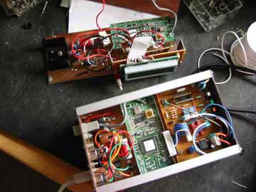
The pictures show one of the results of the experiments: a tracker for APRS using the GST-2 translator by Byonics . together with a small display unit with information about the speed, direction and location (in lat. and long.) The PIC is running the Tiny Track software.
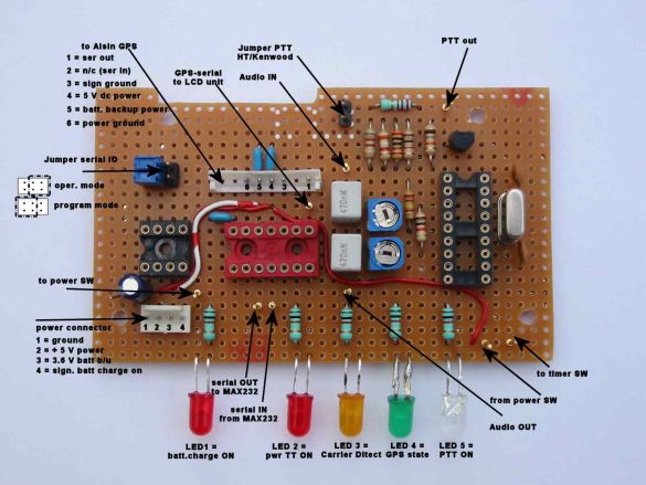
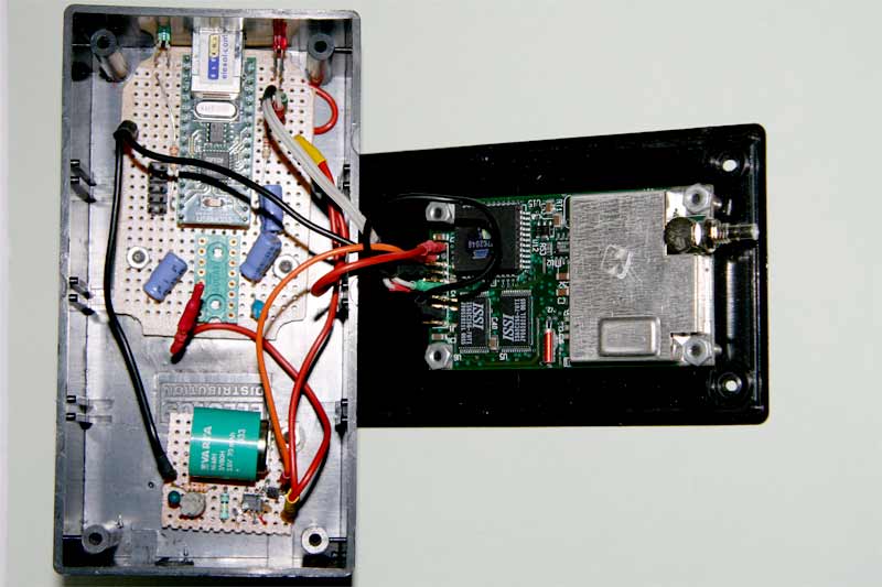
As I never make PC boards for one off projects this tracker was made on perf board - see the picture with the lay out. On this board the black socket holds the 16F84 for the TinyTrak 1. The red socket holds the 7404 of which two sections are used. To interface with a computer I used the MAX232 chip on the Aisin board. With a small hacksaw I took that section out and connected input and output (to the TT and GST-T straight to the SMD pins of the chip. The connector to the computer (with the cable that came with the set) can be used to connect to a computer at the right RS232 levels. To switch between program mode (computer <> TinyTrak) and operational mode (GST-2 > computer) I used jumpers. The 8 pin socket holds the GST-2 Aisin>NMEA converter. Wiring is done with wire wrap wire soldered to IC socket pins and component leads. |
On the right you can see what I did with the Jupiter engine. I just linked the engine output (NMEA) to a serial/USB converter that can be linked to a laptop. The IC socket on the USB board is wired for a RS-232 interface so that also a com-port can be used. But as most laptops come with USB only these days that is a bit outdated (that is why there is no chip in the socket...)
However... we got a TomTom navigator in the car now, so why bother.... |
Click on the picture to view in a larger format. |
If you are interested in one of my projects, the components used or more details than given on these web pages you are welcome to contact me. Please feel free to use the web mail facility on this web site.
|
|
| Web Design and hosting by HTO Webservices. Copyright Henk Tobbe - 2007-2008 |
|
Go to the top of the page |
|